From: pv magazine, November edition
Given the vital importance of reliable and verifiable flash test results, it remains a key stage in both cell and module production. With flash results essentially dictating how much a cell/module manufacturer can charge for its products, the results of a flash test must be trustworthy and replicable – even for new and emerging technologies.
New concepts in PV manufacturing mean new requirements for flash testing tools – whether it involves longer flash durations required to characterize high efficiency products, light sources positioned to measure both sides of bifacial technology, or machinery able to test PV modules of odd shapes and sizes destined for building-integrated projects.
“What we observe in the market at the moment is mainly covered by four topics: bifaciality, contacting on cell level for new interconnection methods, capacitance effects (which we prefer to call carrier lifetime effects), and throughput – one of the main drivers of cost reduction,” says Klaus Ramspeck, R&D director at German testing equipment manufacturer h.a.l.m. elektronik GmbH. “In the longer run, upcoming topics which will affect flashing technology might be the use of multiple junctions, though the development of these cell technologies still leaves some time to adapt flashing systems to their requirements.”
Flashing and bifacial
The development of bifacial modules was described as “the largest step function improvement in project economics for minimal technology risk since the introduction of trackers,” by Jenya Meydbray, Vice President of Solar Technology at Cypress Creek Renewables, speaking at the Bifi PV Workshop held in Denver, USA back in September.
But having both sides of a module active in terms of power generation makes a rethink necessary at several levels of the PV value chain, not least at the flash testing stage. And according to PV InfoLink analyst Corrine Lin, “The market share of bifacial modules is not expected to grow significantly in non-Chinese regions before inspection standards or regulations are confirmed.”
Debate surrounding relevant standards centers on whether both sides of a bifacial cell/module need to be flashed to get an accurate characterization, or whether flashing one side and using a reference module is sufficient. Other issues include whether two-side flashing should be done simultaneously, and whether both light sources should be of the same intensity.
“There is a need to better understand the real performance of bifacial solar modules. The winners in the bifacial PV industry will have the ability to forecast performance with smaller safety margins,” says Elias Garcia, Module Characterization Researcher at Netherlands-based testing equipment supplier Eternal Sun. “The International Electrotechnical Commission (IEC) is developing an extension of the standard regarding the I-V measurement of bifacial PV devices. Eternal Sun has two active members within the IEC Technical Committee 82 Working Group 2, in charge of [the standard], and has actively contributed to its development.”
Sunny side up
The current draft IEC standard for bifacial testing (IEC TC 60904-1-2 ED1) describes both one and two-sided illuminations as appropriate for bifacial products, and flashing equipment suppliers are pursuing varied methods.
Finland-based testing equipment supplier Endeas has opted for single-side illumination in its Quicksun 600 tool: “Accordingly, risks associated with double-sided illumination like interference of two simulators with each other (e.g. albedo of both), influence of module transmittance, and the draft standard’s requirement to perform three separate flash measurements in production are avoided,” explains Jaakko Hyvärinen, Managing Director at Endeas. “In addition, the uncertainty calculation required by the standard is a lot more complicated (and uncertain) for measurements with double-sided simulators.”
“Single-sided testing is a good solution when an applicable reference module is used, and the procedure described in the bifacial standard is applied,” continues Hyvärinen. “The reference module has to be identical to the tested modules because single-sided illumination is not sensitive to rear side differences like, for example, unintentional shading. However, this deficiency is a minor complication compared with the complexity and price of a double-sided simulator.”
“The two main testing methods considered are double-sided illumination, where the front side is irradiated at 1,000 W/m2 and the rear side at 0, 100, and 200 W/m², and single-sided illumination, where only the front side receives light, at an irradiance equivalent to that of the double-sided method,” explains Garcia. “Eternal Sun sees a trend of single-sided measurement with values close to 1,200 W/m² used for both in-line production quality checks. and R&D purposes.”
Single-sided flashing also has an advantage when it comes to production cost for manufacturers. Adding an additional light source to test the rear side will increase both the initial capex cost of the tool, and the operating cost – with the need to replace consumables such as xenon lamps or LEDs over time.
Over easy
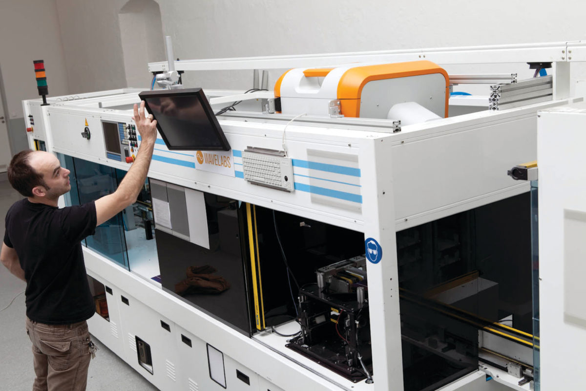
Some other manufacturers, however, believe that flashing needs to be carried out on both sides, in order to accurately characterize a cell or module. “Seeing that modules and cells currently have large variance in bifaciality, for us, you need two sides for an accurate understanding of performance,” states Jason Nutter, sales manager at LED testing equipment supplier Wavelabs. “If all modules were manufactured under ideal conditions, with a tight band of variation in bifaciality – you could get away with a single-sided tester. The reality is that production is not always ideal, and if you flash only from one side, it is hard to know what the root cause is.”
“The advantage of testing bifacial cells and modules using two independent light sources is the direct and individual measurement of the bifaciality of each individual device in one measurement setup,” adds Ramspeck of h.a.l.m. “Only when both sides are measured, [does] it become possible to really sell the rear side efficiency as an additive to STC [standard test conditions] power output. Furthermore, quality control and calibration become easier.”
Italian PV equipment manufacturer Ecoprogetti launched its Ecosun bifacial flasher earlier this year, an all LED tool with two-sided flashing. “Operating in such a way [flashing only the front side], it is not possible to analyze the real behavior of the front and rear side of the panel working at the same time,” says R&D & Electrical Engineer Federico Quartiani. “Ecoprogetti has developed a testing solution which is also capable of settling the issue and we believe it will become the new standard testing machine.”
Vital statistics
The key metric in bifacial measurement is the bifaciality coefficient – the ratio of the output measured from the rear side of a cell/module to the output measured from its front side. In December 2017, Chinese module manufacturer Longi Solar Technology Co. Ltd claimed a world record 82.15% bifaciality for its PERC mono c-Si cell Hi-MO2, a record certified by China’s National Center of Supervision and Inspection on Solar Photovoltaic Product Quality (CPVT).
“The bifacial performance of a device is very simply characterized. Key metrics are: standard test conditions front side power output; and bifaciality coefficients,” explains h.a.l.m.’s Ramspeck. “Furthermore, work has started to define bifacial standard conditions, namely irradiation and spectral distribution for a standardized measurement under bifacial illumination. This will be a very important step to achieve similar comparability as for front side STC measurements, which also do not cover real conditions, and are nevertheless totally accepted in the community.”
Opinions continue to vary between manufacturers as to the intensity of light with which the rear side should be tested. For the front side of a module, standard test conditions of 1,000 W/m² (‘one sun’) of irradiance with distribution according to the air mass (AM) 1.5 global spectrum, and a device temperature of 25°C have long been established. For the rear side, however, it is less clear how best to measure performance, since the amount of light likely to fall on the rear side of a module will inevitably differ greatly between installations.
Two positions on this issue appear prevalent among flasher manufacturers – that the rear side should be illuminated at 200 W/m², assuming around 20% as much light will reach the rear side as the front; and flashing at an equal 1,000 W/m², accepting there is some possibility that both sides could receive the same irradiation in the field. It seems likely at this point that a testing standard could involve a combination of the two.
“We think it should be obligatory to flash at one sun intensity from both sides. Some modules will be installed at angles and in settings where there is the possibility to get equal sun on both sides,” says Wavelabs sales manager Jason Nutter. “Although a lower back side flash lowers the cost of the tool, it assumes an arbitrary 20% for the backside, but you don’t know that – it depends where the modules are installed.”
“The standard we see developing is a one sun flash and a 0.2 sun flash from both sides,” continues Nutter. “Then you can get a real understanding of a module’s installed performance, and what happens in combinations with less intensity on one side – modules can be installed in a perpendicular orientation, hence the importance of these tests.”
Future applications
Taken further, the idea of flashing modules at multiple intensities could lead to flash testing for a variety of different light conditions becoming more popular. “Light reflected to the rear side of the module is the biggest variable, so it’s important to [supply] the client with the possibility to replicate as many test conditions as possible,” says Ecoprogetti’s Federico Quartiani. “To have a flexible model of the installation environment, and to arrange a high level of irradiation on the rear side are key elements for the future development of metrics for measuring bifacial performance.”
“A large number of modules are not used under AM 1.5 spectrum,” agrees Jason Nutter. “We have the ability to test each module under different spectra with little impact on throughput. Just load in different spectra based on possible geographic locations and test. Manufacturers could then sort their modules by performance under particular conditions, and even be able to deliver to the most appropriate projects.”
This content is protected by copyright and may not be reused. If you want to cooperate with us and would like to reuse some of our content, please contact: editors@pv-magazine.com.




By submitting this form you agree to pv magazine using your data for the purposes of publishing your comment.
Your personal data will only be disclosed or otherwise transmitted to third parties for the purposes of spam filtering or if this is necessary for technical maintenance of the website. Any other transfer to third parties will not take place unless this is justified on the basis of applicable data protection regulations or if pv magazine is legally obliged to do so.
You may revoke this consent at any time with effect for the future, in which case your personal data will be deleted immediately. Otherwise, your data will be deleted if pv magazine has processed your request or the purpose of data storage is fulfilled.
Further information on data privacy can be found in our Data Protection Policy.