From pv magazine 04/2021
It is safe to say that utterly fault-free operation of solar plants is impossible. Sooner or later, modules, connectors, and inverters will experience some form of trouble, as would be the case for any other technical appliance. What makes solar arrays unique in this respect is that they require little attention from human operators. Once installed at a sunny location, operators watch over performance metrics from afar, with engineering crews visiting the site periodically. That makes things easy, but also brings the question of failure detection to the fore. Module-level power electronics (MLPE) offer visibility of anomalies in unmatched granularity – a strong value proposition, one would think. Still, despite MLPE suppliers having increased their market share in the C&I and to some degree in the ground-mounted segment, the industry remains wary of the devices’ cost and use.
“MLPE can give you a first good indicative data point,” explains Jenya Meybray, CEO of PV Evolution Labs. “But not all of them can. It is important to distinguish between power optimizers, microinverters, string combiners and rapid shutdown devices, for example.” Meydbray further explains that anything performance-related can be picked up by module-level power electronics better than by string-level monitoring. On top of that, the essential differences in a device’s ability to detect faults is dependent on the availability of distributed maximum power point tracking (see table, right).
To detect faults at string level, the inverter will measure the string voltage and current and compare it to a reference point. That is usually a neighboring parallel string, or a performance assumption made with temperature and irradiance sensors. An MLPE device with MPPT function does the same, but on module level, comparing two modules next to each other. This presents a decisive advantage, because string voltage adds up from module to module, and the current is adjusted for all the modules in a string. That makes it near impossible to detect outliers within a string.
“In the case of yellowing of the encapsulant, for example, a power optimizer would be able to detect that the current drops, but the voltage stays the same for a module, because of the reduced irradiation on the cell,” explains Meydbray. “String level monitoring would be less granular, and it is more likely that some of these faults are hidden behind the ‘noise’ in the string.”
Another example of faults that can be well detected using MLPE is potential induced degradation (PID). This failure mode, caused by leakage currents between the semiconductor and frame and mounting structure, leads to sodium-ions attacking the passivation layer – sometimes irreversibly. Because PID is caused by a potential between the semiconductor and the structure, the problem is more pronounced in modules that are physically closer to the positive pole of a string.
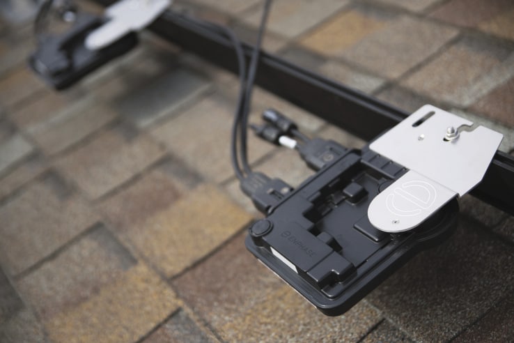
Inverter manufacturer SolarEdge Technologies is known for its use of DC power optimizers, and advertises that its system can detect PID. Microinverters like Enphase solutions, on the other hand, would eliminate the problem because each module has its own inverter, and thus runs on a low voltage and therefore a low potential to its surroundings. With power point tracking MLPE, it would be easy to identify such a pattern because an operator can see how each module performs.
In contrast, string-level monitoring can only tell that a string is down on power. If parallel strings are somewhat equally affected, it would be tough to spot the problem. That is especially true if the performance loss is marginal – though that does not mean that the financial damage this incurs would be marginal.
In February, energy consultancy DNV GL published a paper on predictive maintenance in the solar industry. Here the consultants made a calculation asserting that for a 100 MW site, exposed to 2,500 hours of irradiance per year, and financed through a €35/MWh PPA, a performance loss of a mere 1.6%, would incur financial losses to the tune of €140,000 per year. The argument that MLPE proves its economic case if it is cheaper than the damage to equip a 100 MW site with monitoring MLPE seems apparent, but it may not be complete.
DNV GL focused its analysis on inverter-related failures, and in recent years, these have been the dominant failure point in solar arrays. Though the example still shows the considerable financial impacts of what seem to be marginal losses, it also demonstrates the industry’s hesitation to adopt MLPE. Adding power electronics to each module drastically increases the number of potential failure points. But this problem is not unique to MLPE.
“I have been told by a project developer in California that the failure rate for their monitoring systems was 100%,” Meydbray recalls. “At some point sooner or later they all experience some downtime.” Similarly, a faulty monitoring system would cause a truck roll, and if the asset operator is unlucky, a lengthy troubleshooting process.
Of course, on top of that financial consideration, it only works if MLPE can find any failure in a solar plant. And even if it was possible to identify performance issues, the data that MLPE usually produces won’t stand should there be a dispute over warranty claims – the modules in question would still need to go to a testing lab.
| Degradation mode | MPLE with MPPT | MPLE without MPPT |
| Corrosion of cell metallization Solder joint degradation Corrosion of busbars LeTID PID Excessive LID (>3%) Cracked cells |
Yes These degradation modes can impact current and voltage, so module-level monitoring with MPPT can identify outliers |
Maybe MLPE with monitoring can detect module-level voltage degradation, but it cannot detect current degradation |
| Cracked cells Bypass diode failure |
Yes 1/3 of module voltage is lost if a diode is shorted |
Yes 1/3 of module voltage is lost if a diode is shorted |
| Discoloration of frame, junction box, or polymeric materials |
No | No |
| Junction box failure Backsheet stack layer delamination, embrittlement or cracking Glass fracture |
Yes, but only if a ground fault occurs Safety risks will be reduced due to low voltages |
Yes, but only if a ground fault occurs Safety risks will be reduced due to low voltages |
| Encapsulant yellowing | Yes Yellowing causes loss of current |
No |
| Frame tape or frame adhesive failure Delamination |
No | No |
| Table : PV Evolution Labs | ||
This content is protected by copyright and may not be reused. If you want to cooperate with us and would like to reuse some of our content, please contact: editors@pv-magazine.com.


1 comment
By submitting this form you agree to pv magazine using your data for the purposes of publishing your comment.
Your personal data will only be disclosed or otherwise transmitted to third parties for the purposes of spam filtering or if this is necessary for technical maintenance of the website. Any other transfer to third parties will not take place unless this is justified on the basis of applicable data protection regulations or if pv magazine is legally obliged to do so.
You may revoke this consent at any time with effect for the future, in which case your personal data will be deleted immediately. Otherwise, your data will be deleted if pv magazine has processed your request or the purpose of data storage is fulfilled.
Further information on data privacy can be found in our Data Protection Policy.